

瀚文The smart keyboard is a keyboard I designed for my own use Multifunction,modular mechanical keyboard.The keyboard uses a modular design, the leftMultifunctional scene interaction moduleCan be replaced with a variety of custom components, the default is a one with an e-ink screen and a FOC force feedback knob
Dynamic组件;The keyboard uses the keyboard firmware and module firmware based on the ARM Cortex-M chip developed by me; the keyboard body uses the shift register method to realize the optimized key scanning circuit; the module and the keyboard body can be used alone or communicate with each other through the serial port protocol and call.The contents of the open source materials in this repository include:
- 10 PCB design source files of Hanwen font hardware design, providing the file format of Lichuang EDA Professional Edition
- Shell Design Structure File
- The firmware source code of the keyboard body (relatively perfect)
- Firmware source code of Dynamic component (framework completed, more APP extension WIP)
- Keyboard secondary development SDK (under development)
The keyboard function demonstration can refer to:
Note: Issues discuss topics related to project development, don’t send meaningless messages in it, otherwise people who watch the warehouse will receive notification emails, which will cause trouble to others! ! ! Irrigation can be discussed in Discuss in the warehouse!
1. Project Description
1.0 Update Notes:
22.8.13 Update:
- The new proofing PCB has been received, but due to the video posted by He this week, in order to avoid unnecessary pressure, he decided to stagger the peak and update the PCB project next Saturday (doge).
22.7.31 Update:
- Add all the design schematic files of the keyboard hardware (there are still some bugs in the circuit that have not been fixed, such as the flying wires in the video, which will be updated later when the new version of the PCB proofing is received and verified without problems)
- Add keyboard firmware source code
- Add Dynamic component source code
1.1 Description of the project file:
1.1.1 Hardware
In the Hardware folder are the schematic diagrams and PCB files of all the circuits used in the Hanwen keyboard. Currently, the source files in Lichuang EDA format and the light drawing files in Gerber format are provided for direct processing by manufacturers.
There are a total of the following boards:
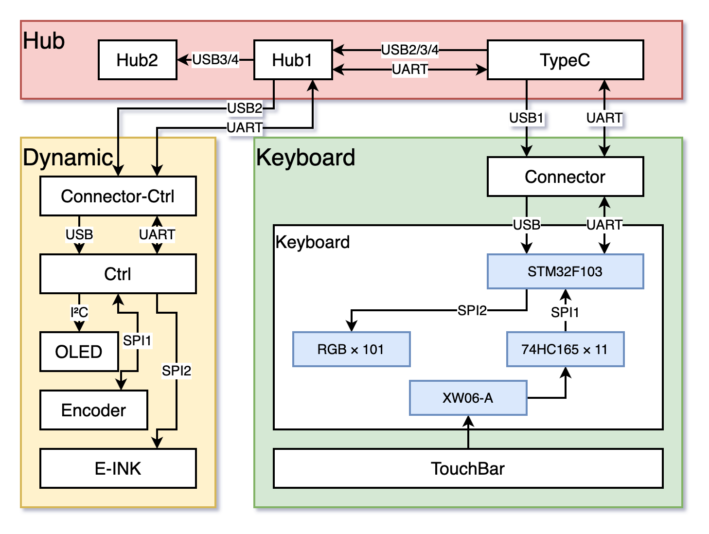
- HelloWord-Keyboard: The PCB of the main keyboard, the controller is STM32F103, which can be used alone with the base, provides conventional key input function, and has independent RGB lights for all keys.
- HelloWord-Ctrl: The PCB of the left Dynamic component, the controller is STM32F405, which can be used alone with the base, providing FOC force feedback knob, electronic ink screen display, OLED display, RGB lights and other functions.
- HelloWord-Connector: The main keyboard is used to connect the contact PCB of the base, and is connected to the keyboard PCB through the FFC cable.
- HelloWord-Connector-Ctrl: The Dynamic component is used to connect the contact PCB of the base, and is connected to the Dynamic component PCB through the FFC cable.
- HelloWord-Encoder: Magnetic encoder PCB, used for position feedback of brushless motor, needs to work with a radially magnetized permanent magnet.
- HelloWord-Hub1: The two extra USB-A ports extended on the base are connected to the PCB, and are connected to the TypeC interface board through the FFC cable.
- HelloWord-Hub2: The female PCB of the two extra USB-A interfaces extended on the base is reserved for the USB3.0 female socket and pins, but only the 2.0 interface is currently used, and it can be upgraded to a USB3.0 HUB in the future.
- HelloWord-TypeC: The TypeC interface PCB on the base is used to connect to the computer, and the power charging management chip and the USB-HUB chip are onboard, and the other modules are connected through the FFC cable.
- HelloWord-OLED: The minimum driver circuit and adapter board for the OLED screen on the Dynamic component.
- HelloWord-TouchBar: Optional capacitive touch bar module PCB, which uses 6-button capacitive touch chips to form a linear sensing array, which is connected to the main keyboard PCB through FFC cables.
1.1.2 Firmware
Firmware provides the firmware source code of all the above boards, andPrecompiled bin firmwareIt can be burned directly, mainly including the following two projects:
- HelloWord-Keyboard-fw: The firmware of the main keyboard, mainly realizes high-speed key scanning based on hardware SPI and shift register, bus RGB light control based on hardware SPI & DMA, HID high-speed device keyboard enumeration & message protocol implementation, non-volatile storage configuration, multiple Layer key mapping and other functions.
- **HelloWord-Dynamic-fw: **Dynamic component firmware, mainly implements FOC-based motor control code, configurable touch-sensitive packaging, e-ink screen driver, OLED driver, USB full-speed composite device enumeration and communication protocol, RGB Light control and other functions.
The projects are all implemented based on STM32HAL, so the corresponding.iocThe file can be opened with STM32CubeMX by itself to generate the corresponding keil or STM32IDE project file. You can also compile and download with CLion or STM32CubeIDE like me.
_ReleaseThe folder is a precompiled bin file, you can useST-Link UtilityOr software such as STM32CubeProgrammer can be downloaded directly to the chip.
The implementation details of the firmware are explained later.
For the method of turning CLion into an IDE for STM32, please refer to a tutorial I posted before: Configuring CLion for STM32 Development[Elegant Embedded Development].
1.1.3 Software
Software provides some computer-side PC software for interacting with the keyboard, including the PC software for foolishly modifying the picture of the ink screen demonstrated in the video, and will be gradually supplemented in the future.Graphical software for modifying key positionsGiveModule add APPapp store software, which are still in development.
1.1.4 Tools
Tools mainly provides some third-party tool software, such asSTM32 ST-LINK Utility for installing the driverzadigand many more.
1.1.5 3D Model
In the folder are the 3D model files of all the structural parts used in the keyboard, which can be used for 3D printing.
1.1.6 Docs
Relevant reference documents, including the chip’s Datasheet, etc.
2. Hardware Architecture Description
About structural design?
The structure of Hanwen consists of three parts:docking station,keyboard input moduleandReplaceable multifunctional interactive modulethe keyboard input module and the replaceable multifunctional interaction module are connected on the top of the docking station base through several contact contacts:

The keyboard body is also a standard customized keyboard laminated structure design, including shock-absorbing cotton, PCBA, positioning plate, shaft underpad, etc.:

The structural design of the keyboard is mainly modified by Xikii according to the S98. It is a 75-key layout. Students who need other layouts can modify the PCB and firmware adaptation by themselves.
Regarding the structural parts shown in the video, it is not easy for me to release the source files without authorization because it is Xikii’s solution, and the original version of the structure is used for CNC machining, so the cost will be relatively high.
So I also asked Xikii to help design a simplified version of structural parts that can be used in 3D, and open source it and put it in the warehouse.
About chip selection?
- The chip selected for the keyboard master is STM32F103CBT6. In fact, C8T6 can also be used. However, considering the scalability of future firmware functions, CBT6 with twice the size of Flash is more cost-effective. Since my firmware is basically implemented using the HAL library, in fact, the main control can also be replaced with any chip of the STM32 series. The support chip needs to have 2 SPI hardware interfaces for key scanning and RGB light driving respectively. , and a full-speed USB interface.
- The STM32F4 controlled by the Dynamic component, this is because I have a lot of this chip at hand, and theoretically it can be replaced with a more cost-effective F1 series, as long as the chip has an advanced timer for PWM generation and 2 hardware SPI interfaces for coding Communication with the e-ink screen, an I2C interface for the OLED driver, and a full-speed USB interface are enough.
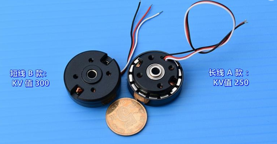
- The magnetic encoder chip of the motor is AS5047P, which is also a very commonly used magnetic encoder chip with good performance, but the cost is slightly higher. I just chose this one because I have it at hand, and it can also be modified to other cheaper models. Such as MT6816, of course, also need to modify the firmware driver code.
- The 74HC165 used in the shift register for key scanning is about 0.5 yuan per piece for domestic chip retail, and one piece can drive 8 keys. You can modify the serial register chip according to the number of keys you need. The imported 165, such as TI, is more expensive than the domestic one, and the performance will be slightly better. However, since the key scan frequency of 4MHz is sufficient in this project, even the domestic 16MHz chip is more than enough.
- The capacitive touch panel is realized by a 6-channel capacitive touch button chip XW06A, which has certain requirements for the design of the PCB induction panel, and the warehouse has provided the designed PCB. The reading method of this chip is actually no different from ordinary buttons, so 74HC165 is also used for scanning and reading in this scheme.
- The motor FOC driver circuit was completely ported from my Ctrl driver, using the FD8288Q as the gate driver, no current sensor needed.
About the burning method?
For programming with debuggers such as JLink and STLink, I have reserved SWD debug ports on both the PCB and the casing. For students who have no experience in hardware development, I will release a Bootloader later, which can be used for firmware upgrade directly through the USB port.
About motor selection?
I am using a 2204 second-hand motor, but this motor does not seem to be easy to buy at present. You can choose a brushless motor of similar size to replace it. In terms of parameters, the KV value needs to be lower, preferably around 200. The motor needs to manually install a radially magnetized permanent magnet on the rotor for encoder positioning. Different types of motors require some adjustments to the FOC parameters.
3. Software Architecture Description
About the way the keys of the keyboard firmware are mapped?
In order to give full play to the advantages of the shift register scanning scheme mentioned in the video, the firmware code decouples the PCB Layout traces and the key scanning sequence, and remaps them through software.That is to say, the connection of the buttons in the PCB can be arbitrary.hw_keyboard.hin the filekeyMap[KEYMAP_NUM][IO_NUMBER]Specify the mapping method in .
This is a two-dimensional array representing
KEYMAP_NUMLayer keymap, each layer hasIO_NUMBERA key (that is, the number of keys on your keyboard); the 0th layer is special, responsible for mapping the random layout of the PCB keys to the keyboard standard key layout, and the subsequent layers 1, 2, 3, 4… are all custom , responsible for mapping standard button layouts to arbitrary layouts.
for example:
Consider the button pointed by the arrow in the schematic diagram. This button can be anywhere on the PCB, but we can see that it is the 10th button from left to right (according to the connection order of 74HC165, that is, the shift scan order). So it is numbered 9 (counting from 0).

If we put it on the actual PCBRight Altposition, then refer to the code in the following figurered boxin layer 1 mapping (aka standard layout) inRIGHT_ALTThe serial number is 76, then the 76th variable mapped in the 0th layer is filled with 9 (blue box).
In this way, all the keys on your PCB are filled in the 0-layer mapping in turn, and a mapped standard keyboard is obtained. Subsequent layers 2, 3, 4, 5, etc. can be modified and added as needed, and there is no need to use number numbers, but it is very convenient to use the enumerated key names directly.
Therefore, for those who want to modify the keyboard layout, they only need to add or delete a few 74HC165 in series on the schematic diagram, then route the PCB at will, and then delete or add some numbers to the 0-layer mapping in the code (for example, in the following In the example, my keyboard is 83 keys); the modification of the following layers is analogous.
through the codekeyboard.Remapfunction to map different layers, such askeyboard.Remap(2)This sentence is to use layer 2 mapping.

About the filtering method of the keyboard firmware?
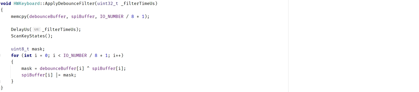
The firmware uses independent filtering for each key, but it is implemented in a very efficient way (after all, for a 1KHz message, the keys are scanned at least twice during each message, which means that the 1000*2*[按键数目] number of filters).
The basic principle is very simple, that is, the reason for the button jitter is that after pressing it, it will jump repeatedly between high and low levels. This stabilization time is generally tens of us (note that it is the level stabilization time, not the button trigger time, the latter is due to caused by the uncertainty of the contact time of the key reed, which may be as long as several ms).
Several filtering methods are described in QMK’s qmk_firmware/feature_debounce_type document, which are divided into Eager and Defer, symmetric and asymmetric, etc.
The default is to useSymmetric Delay Global Filteringthat is to say, the same filtering is performed on all the keys, and the scan data is submitted after all the keys are stable and no longer changed.
Corresponding to it is the aggressive filtering method, that is to say, once the key change is detected, the data is submitted, but no more keys will be responded to within N milliseconds after that (which avoids submitting the jittery keys). This method has a low trigger delay, but is very sensitive to noise and is prone to false triggering.
What I use in Hanwen’s firmware isSymmetric Delay Independent Filteringthat is, each button is detected twice. If the button change is detected for the first time, then the interval of N microseconds (this parameter can be configured, it can be longer than the typical jitter time of the button) is detected again. If the two detection results are consistent , then judging that the button is pressed, at this time, it can be ensured that the button has changed, and the button will not be triggered repeatedly, taking into account the delay and stability.
This process is efficiently processed by XOR operation, just because the button buffer is scanned by the shift register, each bit itself represents a button, so the filtering efficiency is very high, and the measured effect is also very good.
About the HID descriptor for keyboard firmware?
This can directly refer to the source codeusbd_customhid.cIn the file, I have configured two ReportIDs, ID-0 is for reporting key scan data (all keys are not overrun), and ID-1 is reserved for subsequent communication with the host computer to change the key software.
About RGB control?
The single-bus ws2812b series lamp beads are used in the code, and a large number of RGB can be connected in series with one line, and the SPI-DMA simulation timing is realized in the code, and the ultra-high refresh rate is obtained.
At present, only one demo light effect is written in the code (very simple is to poll the color). If you add additional light effects yourself, passkeyboard.SetRgbBufferfunction to set the RGB value, thenSyncLightsJust send the data to the LED:
while (true)
    {
        /*---- This is a demo RGB effect ----*/
        static uint32_t t = 1;
        static bool fadeDir = true;

        fadeDir ? t++ : t--;
        if (t > 250) fadeDir = false;
        else if (t < 1) fadeDir = true;

        for (uint8_t i = 0; i < HWKeyboard::LED_NUMBER; i++)
            keyboard.SetRgbBuffer(i, HWKeyboard::Color_t{(uint8_t) t, 50, 0});
        /*-----------------------------------*/

        // Send RGB buffers to LEDs
        keyboard.SyncLights();
    }
4. SDK design & secondary development
To be added.
Thanks to the following items:
Lexikos/AutoHotkey_L: AutoHotkey – macro-creation and automation-oriented scripting utility for Windows. (github.com)
olikraus/u8g2: U8glib library for monochrome displays, version 2 (github.com)
simplefoc/Arduino FOC for BLDC (github.com)
zhongyang219/TrafficMonitor: This is a desktop floating window software used to display the current network speed, CPU and memory utilization, and supports taskbar display and skin replacement. (github.com)
#HelloWordKeyboard #Hanwen #Smart #Keyboard #multifunctional #modular #mechanical #keyboard #designed
HelloWord-Keyboard: Hanwen Smart Keyboard is a multifunctional, modular mechanical keyboard that I designed for my own use.